The sound power level says how much noise a machine makes. It is the right number for comparing machines and for feeding a room prediction, and it is the wrong number for the person standing at the machine. What that person is exposed to is the emission sound pressure level: the level at the work station, with the background noise taken out and the room’s reflections taken out, so that what is left belongs to the machine.
It is the number a datasheet prints. The noise-emission declaration of ISO 4871 carries beside , and the EU Machinery Directive requires it whenever it exceeds 70 dB(A). Five standards determine it, and they differ in exactly one thing: how they get rid of the room. ISO 11201 qualifies the environment until there is no room to get rid of; ISO 11202 corrects for it approximately, by two routes; ISO 11204 corrects for it accurately; ISO 11203 derives the level from the sound power level, so nothing is measured at the work station itself; and ISO 11205 uses sound intensity, a route this library does not implement.
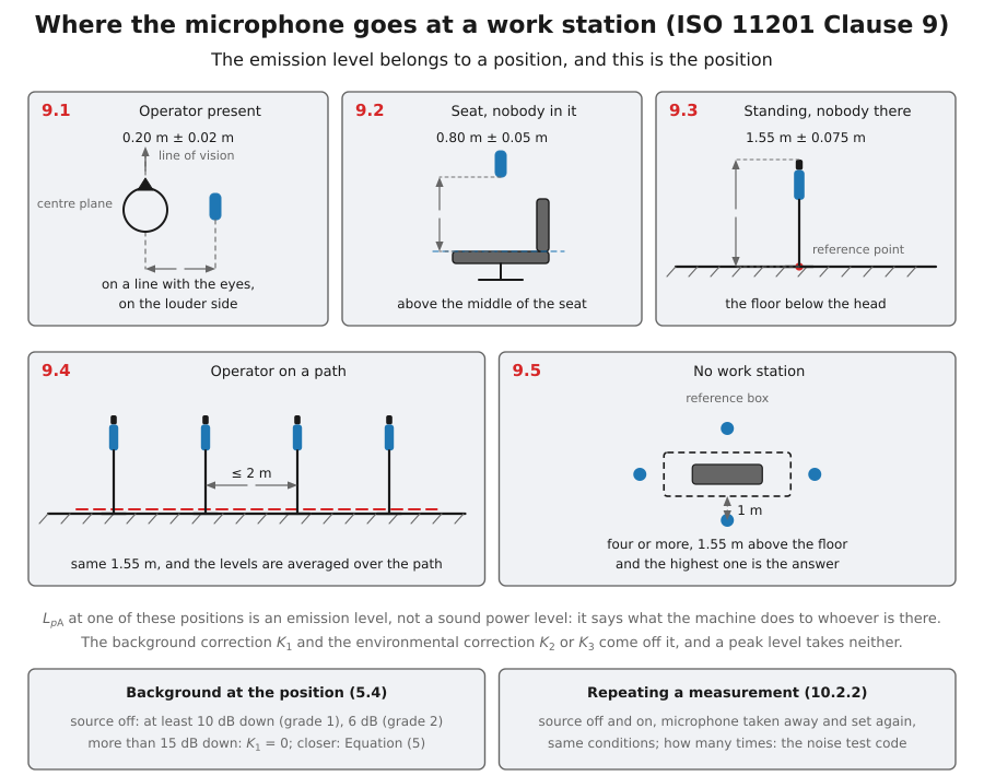
The clause is short and those five cases are all of it: what changes is where the microphone stands, never what is taken off what it reads.
1. How the measurement goes
Section titled “1. How the measurement goes”ISO 11201, ISO 11202 and ISO 11204 print one procedure, almost word for word, and part company only over the room; ISO 11203 measures nothing at the work station and has no procedure of this kind. The clause numbers below are those of ISO 11201 and ISO 11204. ISO 11202 has one clause more ahead of the test environment, so from clause 5 on its numbers are one higher.
-
Test the repeatability, then choose the part. ISO 11200:2014 puts this first (Figure 2): read several times at one of the positions and form the standard deviation of Equation (C.1). Against it stands the of the method, 0.5 dB at grade 1, 1.5 dB at grade 2 and 3 dB at grade 3 (Table 1 of each part): a machine whose own emission wanders by more than that gains nothing from the more exact part. Figure 3 then chooses. With only a class 2 meter, ISO 11202; where the machine can be measured outdoors, in a hemi-anechoic room or in a large hall, ISO 11201; in a very reverberant room and with intensity equipment, ISO 11205; where the sound power level has to be determined anyway, ISO 11204; where one dominating source radiates towards the work station, method A.1 of ISO 11202, which needs no other microphone position; and otherwise method A.2 or ISO 11204.
-
Check the instruments (clause 4). The meter with its microphone, cable and windscreen is class 1 to IEC 61672-1, and any filters are class 1 to IEC 61260. ISO 11201 accepts nothing else; ISO 11202 and ISO 11204 let a class 2 meter in and make the result grade 3 for it (4.1). A class 1 calibrator goes on each microphone before and after each series of measurements: with nothing adjusted in between, the two readings may differ by 0.5 dB at most, and a series that fails that is discarded (4.2).
-
Mount and run the machine (clause 8). As its noise test code says, and exactly as for the sound power determination. Where no code exists the clause lists the modes to choose from (a specified load, full load, idling, maximum speed, the noisiest condition representative of normal use, a simulated load, a characteristic work cycle) and asks for the machine to be stabilized, at a steady temperature, before the first reading (8.5). A machine whose noise follows the ambient temperature, one with a speed-controlled cooling fan for instance, is held at 23 °C ± 2 °C (8.1). What was chosen is recorded in numbers, with the operational periods and the cycle (12.3).
-
Place the microphone (clause 9). One of the five cases of the figure above. The reference direction of the microphone points at the dominant source, and whenever it is practical nobody attends the machine (9.1). Where the level changes strongly from point to point, 9.1 recommends the average over a small surface centred on the work station, 0.5 m by 0.5 m for example.
-
Measure with the machine running (clause 10). , and if it is required, for at least 10 s when the noise is steady and over a whole number of cycles when the machine has one; in frequency bands, 30 s for the bands centred on 160 Hz and below and 10 s from 200 Hz up (10.1). The intervals are the ones used for the sound power level of the same machine. A cycle of unlike periods is measured period by period and summed as in A cycle of operating periods below. For a peak level the interval takes in at least ten impulsive events and the highest peak is the one kept (10.2.3).
-
Measure the background (5.4). The same position and the same meter, with the machine switched off. The difference between the two readings gives , and decides between a determination and an upper bound, by the margins of The background, and where a determination stops being one. It is determined for each work station.
-
Take the room out, the way the part allows. These are the inputs of The room, and the one ratio it comes down to.
- ISO 11201 allows no correction, so the room is qualified instead: indoors at grade 2, the environmental correction of the reference measurement surface through the work station is 2 dB at most, and the machine does not radiate mainly upwards or away from the work station (5.2.2.1).
- Method A.1 of ISO 11202 measures nothing more: with , where is the distance from the work station to the dominant source and comes from the mean absorption coefficient and the total surface of the room (A.1.2). Amendment 1:2020 makes the mean of the shortest and the longest distance to the radiating surface, and never less than 0.5 m.
- Method A.2 of ISO 11202 adds a path round the machine on the reference measurement surface, at half the height of the source, with equally spaced positions, often one on each side. Their energy average, taken from the level at the work station, is the approximate directivity index of Equation (A.2), and of that same surface comes from ISO 3744 or ISO 3746 (A.2.2 and A.2.3).
- ISO 11204 averages over the positions of an enveloping surface, and recommends the very positions of the ISO 3744 or ISO 3746 sound power determination (A.1.1), then takes of that surface or the ratio (A.2 and A.3).
With a correction, a room whose exceeds 7 dB is out of reach of both parts (5.2).
-
Repeat, for . A repetition is the whole act again (10.2.2): the machine switched off and on if that is feasible, the microphone taken away and set up again, then the same interval under the same conditions. For the mounting and the operating conditions are readjusted each time as well, and the readings enter Equation (C.1) as measured, with no correction (11.2). No part prints how many repetitions: a noise test code may, and the case studies of ISO 11200 Annex B use three and five.
-
Correct, grade and report. for the levels and nothing for the peak; the grade from the three gates of What decides the grade; and . A value is rounded to one decimal place only after the last step of the calculation (12.1), and the report states the grade reached beside the level and its expanded uncertainty (clause 13).
2. One law, printed three times
Section titled “2. One law, printed three times”Every measuring part of the group prints the same subtraction:
is what the meter read. removes the background noise, removes the reflections the room sent back, and the difference is the machine. ISO 11201 prints it without the term, not because the term is absent but because its environment is qualified so that the term is negligible: an essentially free field over a reflecting plane has nothing to send back.
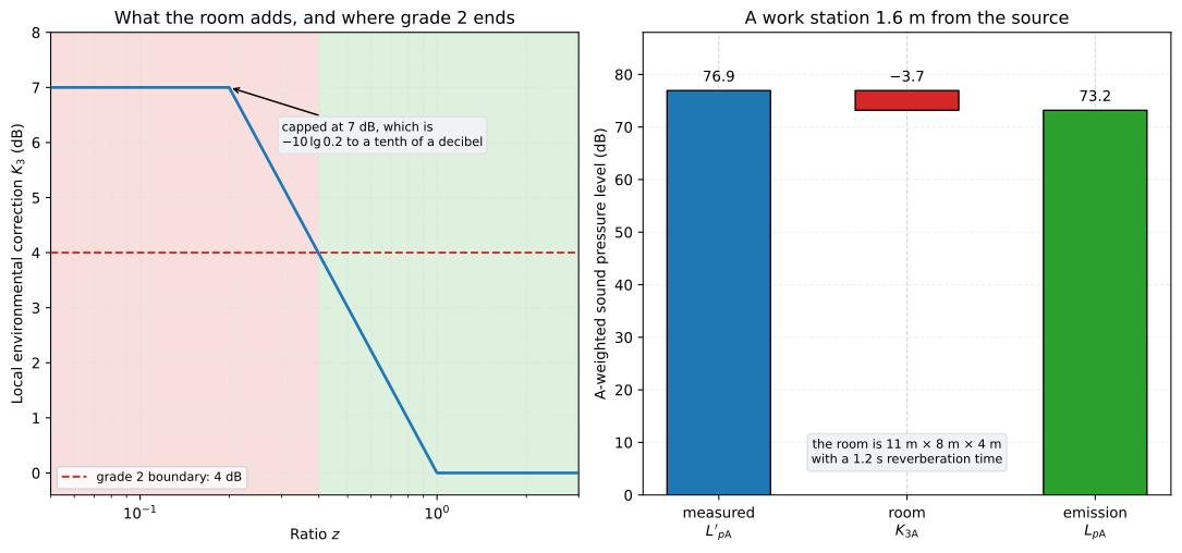
The room correction is capped at 7 dB and vanishes above a ratio of one; where it exceeds 4 dB the determination drops from grade 2 to grade 3.
One rule is absolute and easy to get wrong: a peak level takes no correction at all. ISO 11202 clause 8 and ISO 11204 clause 7 both say so. is reported exactly as measured, because both corrections are derived from mean-square pressures and neither has a meaning for a single largest excursion.
3. The background, and where a determination stops being one
Section titled “3. The background, and where a determination stops being one”The background correction is the same closed form the sound-power side uses,
but this group puts its own thresholds around it. Past 15 dB of margin the background is negligible and is taken as zero. Below 6 dB (grade 2) or 3 dB (grade 3) the correction is held at its value there, and the level stops being a determination and becomes an upper bound. The library returns that fact rather than raising, because the reading is still worth reporting; what it may not do is go out unlabelled.
from phonometry import emission
background = emission.background_noise_correction_at_workstation(79.0, 70.0)print(round(background.correction, 1), background.upper_bound)# 0.6 False
4. The room, and the one ratio it comes down to
Section titled “4. The room, and the one ratio it comes down to”Both ISO 11202 method A.2 and ISO 11204 print the same three lines, a function of one dimensionless ratio :
The 7 dB cap is not a separate rule bolted onto the curve: is 6.99 dB, so the cap is the curve’s own value rounded to the tenth of a decibel the standard prints its corrections to. The upper branch is a floor for the same reason a correction cannot be negative, since a room can only add to what the microphone hears.
Two roads reach , and they are the same road. ISO 11202 Equation (A.4) and ISO 11204 Equation (A.3) go through the environmental correction of the test room and the directivity the work station sees; ISO 11204 Equation (A.6) goes through the equivalent absorption area directly. ISO 11204 A.1.2 says the two rest on the same assumptions, and under the ISO 3744 definition they are identically equal:
import mathfrom phonometry import emission
absorption, surface = 47.0, 16.0          # m^2, the room and the surfacek2 = 10.0 * math.log10(1.0 + 4.0 * surface / absorption)
by_k2 = emission.environmental_ratio_from_k2(k2)by_area = emission.environmental_ratio_from_absorption(absorption, surface)print(round(by_k2, 9) == round(by_area, 9))# True
With no directivity to speak of the expression collapses to , so : a work station that sees the machine no more strongly than the measurement surface does needs the very correction the surface needed. Only up to the cap, though. At dB the ratio reaches 0.2 and the correction stops following: a room with dB still gets dB, because the cap is on and not on the room.
5. What decides the grade
Section titled “5. What decides the grade”Three gates decide it and the worst one wins. A class 2 sound level meter makes
the result grade 3 whatever else is true. The background must clear 6 dB for
grade 2 and 3 dB for grade 3. And the local environmental correction must not
exceed 4 dB: ISO 11202 A.1.3 puts the boundary there directly, on the
correction worked out for the farthest point of the radiating area, and
ISO 11204 5.6 puts it there too. Method A.2 is stricter. Its Condition (A.6) is
that same inequality once (A.4) and (A.5) are substituted into it, with a
margin added to the directivity index because the index is only
approximate: 0.5 dB for a source up to 1 m in its largest dimension, 1 dB up to
3 m and 1.5 dB beyond (A.2.5). Written for , that moves the boundary down
to 3.3 dB, 2.8 dB and 2.4 dB. grade_from_local_correction applies the 4 dB
boundary of A.1.3 by default; give it largest_dimension_m, the largest
dimension of the source, and it reads the margin from that length and applies
Condition (A.6) instead.
from phonometry import emission
print(emission.grade_from_local_correction(3.7))print(emission.grade_from_local_correction(5.2))print(emission.grade_from_local_correction(3.7, largest_dimension_m=0.8))print(emission.grade_from_local_correction(3.2, largest_dimension_m=0.8))# engineering# survey# survey# engineering
The same 3.7 dB is grade 2 by A.1.3 and grade 3 by method A.2 for a source 0.8 m across, whose margin of 0.5 dB stops grade 2 at 3.3 dB. The 4.7 dB of the method A.2 example in ISO 11200:2014 Annex B, for a machine 3 m high, is past both, and its table prints grade 3.
6. The worked example, end to end
Section titled “6. The worked example, end to end”ISO 11200:2014 Annex B prints four case studies with every intermediate value. This is the second: a machine with a clearly identifiable dominating source in an 11 m by 8 m by 4 m assembly workshop whose reverberation time is 1.2 s, with the work station 1.6 m from that source.
import math
import numpy as npfrom phonometry import emission
surface = 2.0 * math.pi * 1.6**2            # the hemisphere around the sourceabsorption = 0.16 * (11.0 * 8.0 * 4.0) / 1.2
ratio = emission.environmental_ratio_from_absorption(absorption, surface)k3 = emission.local_environmental_correction(ratio)
readings = np.array([77.5, 76.0, 77.2, 77.7, 75.9])measured = 10.0 * np.log10(np.mean(np.power(10.0, readings / 10.0)))level = emission.emission_sound_pressure_level(measured, local_correction=k3)
sigma = emission.total_standard_deviation(1.5, 1.0)print(round(k3, 1), round(float(measured), 1), round(float(level), 1))print(round(sigma, 1), round(emission.emission_expanded_uncertainty(sigma), 1))# 3.7 76.9 73.2# 1.8 2.9
Every one of those five numbers is printed in Table B.2, and six conformance rows hold the library to them.
7. A cycle of operating periods
Section titled “7. A cycle of operating periods”A machine that idles, cuts and returns spends a different length of time in each state, and the level of the whole cycle is the energy average weighted by duration rather than by count:
from phonometry import emission
print(round(emission.subinterval_level([80.0, 90.0], [10.0, 1.0]), 1))
Ten seconds at 80 dB carry the same energy as one second at 90, so the cycle lands at 82.6 dB. Counting the two states equally instead would give 87.4.
8. Where the standard argues with itself
Section titled “8. Where the standard argues with itself”The two case studies of Annex B compute the same standard deviation two different ways. Equation (C.1), printed identically in ISO 11201, ISO 11202 and ISO 11204, is the sample standard deviation with ; Table B.3 agrees with it and Table B.1 divides by instead. It is not cosmetic, because the value propagates: with the figure the equation gives, Table B.1’s own expanded uncertainty would be 2.5 dB rather than the 2.4 dB it prints. The library follows the equation and the errata register records the rest.
What this guide covers
Section titled “What this guide covers”Covered
The quantities the ISO 11200 group shares: the emission sound pressure level
L_p = L'_p - K_1 - K_3of ISO 11201 Equation (7), ISO 11202 Equation (10) and ISO 11204 Equation (9); the background correction with this group’s own negligible and minimum margins; the piecewise local environmental correction of ISO 11202 Equation (A.5) and ISO 11204 Equations (A.2) and (A.5), with both printed routes to the ratio it is a function of; the 4 dB grade boundary of ISO 11202 A.1.3 and the margin Condition (A.6) adds to it for method A.2; the total standard deviation and expanded uncertainty; and the duration-weighted summation of a cycle of operating periods.Not covered yet
The measurement is described here, and none of it is computed: the microphone positions of Clause 9 and the qualification of the ISO 11201 environment, the levels round the machine that give ISO 11202 method A.2 and ISO 11204 their directivity index, and the determination of
K_2orAby ISO 3744 or ISO 3746 are carried out by the user, and the library takes their results. The measure of sound propagationQof ISO 11203 and the intensity route of ISO 11205 are not implemented.
References
Section titled “References”- International Organization for Standardization. (1995). Acoustics — Noise emitted by machinery and equipment — Determination of emission sound pressure levels at a work station and at other specified positions from the sound power level (ISO 11203:1995). The route that measures no sound pressure at the work station: L_p = L_W - Q, with Q the only printed expression the document carries.
- International Organization for Standardization. (2010). Acoustics — Noise emitted by machinery and equipment — Determination of emission sound pressure levels at a work station and at other specified positions applying accurate environmental corrections (ISO 11204:2010). The accurate route: Equation (9), the piecewise K3 of Equations (A.2) and (A.5), and the second route to the ratio in Equation (A.6).
- International Organization for Standardization. (2010). Acoustics — Noise emitted by machinery and equipment — Determination of emission sound pressure levels at a work station and at other specified positions applying approximate environmental corrections (ISO 11202:2010). Methods A.1 and A.2: Equation (10), the K3 of Annex A and the 4 dB boundary of A.1.3.
- International Organization for Standardization. (2010). Acoustics — Noise emitted by machinery and equipment — Determination of emission sound pressure levels at a work station and at other specified positions in an essentially free field over a reflecting plane with negligible environmental corrections (ISO 11201:2010). The free-field method: Equation (7), the background correction of 5.4.2 and the uncertainty of clause 11.
- International Organization for Standardization. (2014). Acoustics — Noise emitted by machinery and equipment — Guidelines for the use of basic standards for the determination of emission sound pressure levels at a work station and at other specified positions (ISO 11200:2014). The selection guide for the whole group, and the four worked case studies of Annex B that every number on this page is checked against.